Tuesday, 26 July 2016

TYPES OF CIRCUIT BREAKERS

INSTANTANEOUS MAGNETIC TRIP CIRCUIT BREAKER

As the name indicates, instantaneous magnetic-trip-only
 circuit breakers provide short circuit protection but do not provide overload protection. This type of circuit breaker is typically used in motor control applications where overload protection is provided by an the overload relay.
For example, in the circuit shown below, a three-pole instantaneous magnetic-trip-only circuit breaker provides short circuit protection while the overload protection for the motor is provided by an overload relay which is part of a motor starter.

THERMAL MAGNETIC  CIRCUIT BREAKER

This type of circuit breaker is called a thermal-magnetic
 circuit breaker because it has a trip unit that senses heat to detect an overload and senses a magnetic field generated by current to detect a short circuit.
As described in the Circuit Breaker Design portion of this book, this type of circuit breaker trips immediately when a short circuit occurs, but delays an appropriate amount of time before tripping in the event of an overload.

INTERCHANGEABLE TRIP CIRCUIT BREAKER

The user cannot change the trip unit on many circuit breakers,
Circuit Breakers but some circuit breakers have an interchangeable trip feature. This feature allows the user to change the continuous current rating of the breaker without replacing the breaker. This is done by replacing the trip unit with one of a different rating.

MOLDED CASE SWITCH

Siemens molded case switches employ the same operating mechanism as the thermal magnetic and magnetic only units. However, a preset instantaneous function is factory installed to allow the switch to trip and protect itself at a high fault current, but the switch provides no thermal overload protection or short circuit protection

CURRENT LIMITING CIRCUIT  BREAKERS

Many electrical power distribution systems can deliver large
 short circuit currents to electrical equipment. This high current can cause extensive damage. Current limiting circuit breakers protect expensive equipment by significantly reducing the current flowing in the faulted circuit.
One way to accomplish current limiting is with an additional set of contacts that feature two moveable arms. These are referred to as dual-pivot contacts, which separate even more quickly than the single-pivot contacts. The dual-pivot contacts are connected in series with the single-pivot contacts. As with the single-pivot design, current flows in opposite directions through the contact arms, creating a magnetic repulsion. As current increases, the magnetic repulsion force increases.
In an overload condition where current may only be one to six times normal current, the contacts remain closed until the breaker trips. When a short circuit occurs, fault current is extremely high and both sets of contact arms open simultaneously, generating high impedance arcs. The contact gap of the dual-pivot contacts increases more rapidly, therefore generating arc impedance more rapidly. Once the arcs are extinguished, the dual-pivot contacts close on their own due to spring tension. The single-pivot contacts are held open by the breaker mechanism, which will have tripped during the fault and must be manually reset.
The frame on current limiting circuit breakers of this design is extended to allow room for the dual-pivot set of contacts. Siemens current limiting breakers can handle fault currents of up to 200,000 amps.

SOLID STATE CIRCUIT BREAKERS

Solid state circuit breakers function similarly to thermal-magnetic breakers and have a mechanical breaker mechanism, but incorporate a solid state trip unit. The solid state trip unit allows this type of circuit breaker to have programmable features and a greater degree of accuracy and repeatability.
Similar to other types of trip units, the solid state trip unit:
• Senses magnitude of current flow
• Determines when current becomes excessive
• Determines when to send a trip signal to the breaker mechanism
The brains of a solid state trip unit is a microprocessor. Adjustments on the trip unit allow the user to select numerical values the microprocessor will use in performing protective functions. Current sensors mounted in the trip unit monitor the value of load current. The value of current is reduced to a low level and converted to a digital voltage, which is used by the microprocessor. The microprocessor continuously compares the line current with the value set by the user. When current exceeds a preset value for the selected time, the trip unit sends a signal to a magnetic latch. The magnetic latch opens the breaker’s contacts, disconnecting the protected circuit from the power source.


OVER CURRENT PROTECTION DEVIVCES

Circuit protection would be unnecessary if overloads and short circuits could be eliminated. Unfortunately, overloads and short circuits do occur. To protect a circuit against these currents, a protective device must determine when a fault condition develops and automatically disconnect the electrical equipment from the voltage source. An overcurrent protection device must be able to recognize the difference between overcurrents and short circuits and respond in the proper way. Slight overcurrents can be allowed to continue for some period of time, but as the current magnitude increases, the protection device must open faster. Short circuits must be interrupted instantaneously. Several devices are available to accomplish this.

FUSE

 A fuse is a one-shot device. The heat produced by overcurrent causes the current carrying element to melt open, disconnecting the load from the source voltage.

 NON TIME DELAY FUSES

Fuses without time delay provide excellent short circuit protection. When an overcurrent situation occurs, heat builds up rapidly in the fuse. Fuses without time delay usually hold 500% of their rating for approximately one-fourth second, after which the current carrying element melts. This means that these fuses cannot be used in motor circuits which often have inrush currents of greater than 500%.


TIME DELAY FUSES

Time-delay fuses provide overload and short circuit protection. Time-delay fuses usually allow five times the rated current for up to ten seconds to allow motors to start.

CIRCUIT BREAKERS

The National Electrical Code® defines a circuit breaker as a device designed to open and close a circuit by nonautomatic means and to open the circuit automatically on a predetermined overcurrent without damage to itself when properly applied within its rating. (Article 1 00-Definitions)
Circuit breakers provide a manual means of energizing and de-energizing a circuit. In addition, circuit breakers provide automatic overcurrent protection of a circuit. A circuit breaker allows a circuit to be reactivated quickly after a short circuit or overload is cleared. Unlike fuses which must be replaced when they open, a simple flip of the breaker’s operating handle restores the circuit.
All circuit breakers perform the following functions:

• SENSE when an overcurrent occurs.
• MEASURE the amount of overcurrent.
• ACT by tripping the circuit breaker in a time frame necessary to prevent damage to itself and the associated load cables.

CIRCUIT BREAKER OPERATION

In the following illustration, an AC motor is connected through a circuit breaker to a voltage source. When the circuit breaker is closed, a complete path for current exists between the voltage source and the motor allowing the motor to run. Opening the circuit breaker breaks the path of current flow and the motor stops. The circuit breaker will open automatically during a fault, or can be manually opened. After the fault has been cleared, the breaker can be closed allowing the motor to operate.

REGEN VS DYNAMIC BRAKING

Regen and dynamic braking provide the same amount of braking power to slow a motor from maximum speed in field weakening to base speed. This is because field strength increases until the motor reaches base speed. However, from base speed to stop, regen is capable of slowing a motor at a faster rate. In addition, regen can develop torque at zero speed to bring the motor to a complete stop.
Another advantage of regen is that regen braking is not limited in duty cycle and cool-down periods. Applications that require frequent braking or have overhauling loads should consider four quadrant operation with regen braking.

BASIC OF DC DRIVE OPERATION

CONTROLLING A DC MOTOR

A thyristor bridge is a technique commonly used to control the speed of a DC motor by varying the DC voltage.


It is important to note that the voltage applied to a DC motor must not be greater than the rated nameplate. Armature windings are commonly wound for 500 VDC. The control logic in the drive must be adjusted to limit available DC voltage to 0 - 500 VDC. Likewise, the shunt field must be limited to the motor’s nameplate value.
BASIC OPERATION

A DC drive supplies voltage to the motor to operate at a desired speed. The motor draws current from this power source in proportion to the torque (load) applied to the motor shaft.

100% SPEED 0% LOAD

In this example an unloaded motor connected to a DC drive is being operated at 100% speed. The amount of armature current (Ia) and unloaded motor needs to operate is negligible. For the purpose of explanation a value of 0 amps is used.
The DC drive will supply only the voltage required to operate the motor at 100% speed. We have already learned the amount of voltage is controlled by the gating angle (COSα) of the thyristors. In this example 450 VDC is sufficient. The motor accelerates until CEMF reaches a value of Va - IaRa. Remember that Va = IaRa + CEMF. In this example IaRa is 0, therefore CEMF will be approximately 450 VDC.

100% SPEED 100% LOAD

A fully loaded motor requires 100% of rated armature current at 100% speed. Current flowing through the armature circuit will cause a voltage drop across the armature resistance (Ra). Full voltage (500 VDC) must be applied to a fully loaded motor to operate at 100% speed. To accomplish this, thyristors are gated earlier in the sine wave (36.37°).
The DC drive will supply the voltage required to operate the motor at 100% speed. The motor accelerates until CEMF reaches a value of Va - IaRa. Remember that Va = IaRa + CEMF. In this example armature current (Ia) is 100% and Ra will drop some amount of voltage. If we assume that current and resistance is such that Ra drops 50 VDC, CEMF will be 450 VDC.
1 QUAD,4 QUAD

Up to this point we have only looked at a drive in single-quadrant operation. A single-quadrant DC drive will have six thyristors.
In the speed-torque chart there are four quadrants of operation according to direction of rotation and direction of torque. A four-quadrant DC drive will have twelve thyristors.


SINGLE QUADRANT OPERATION

Single-quadrant drives only operate in quadrant I. Motor torque (M) is developed in the forward or clockwise (CW) direction to drive the motor at the desired speed (N). This is similar to driving a car forward on a flat surface from standstill to a desired speed. It takes more forward or motoring torque to accelerate the car from zero to the desired speed. Once the car is at desired speed your foot can be let off the accelerator a little. When the car comes to an incline a little more gas, controlled by the accelerator, maintains speed. To slow or stop a motor in single-quadrant operation the drive lets the motor coast.
CHANGING DIRECTION OF A DC MOTOR

There are two ways to change the direction of a dc motor

1. Reverse Armature Polarity
2. Reverse Field Polarity


REVERSING IN SINGLE QUADRANT OPERATION

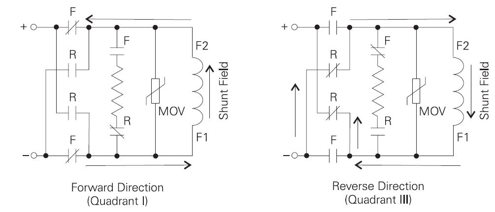
Field contactor reverse kits can be used to provide bidirectional
 rotation from a single-quadrant drive. To turn the motor in the forward direction the “F” contacts are closed, applying DC voltage in one polarity across the shunt field. Simply reversing the polarity of the field, by opening the “F” contacts and closing the “R” contacts, will reverse direction of a DC motor.
It is important to note that field reversal will only work when a quick reversal is not required. The field circuit is inductive and must be brought to 0 current before opening the contacts.

STOPPING A MOTOR

Stopping a motor in single-quadrant operation can be done by simply removing voltage to the motor and allowing the motor to coast to a stop. Alternatively, voltage can be reduced gradually until the motor is at a stop. The amount of time required to stop a motor depends on the inertia of the motor and connected load. The more inertia the longer the time.

DYNAMIC BRAKING

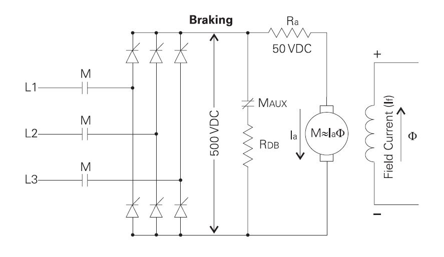
Dynamic braking is often used on single quadrant drives as a means of stopping a motor quickly. Dynamic braking is not recommended for continuous or repetitive operation. Dynamic braking kits for use with Siemens  drives are typically designed to stop a load operating at base speed a maximum of three consecutive times. After three consecutive stops a waiting period of 15 minutes is required.
Dynamic braking develops stopping torque by using a contact (MAUX) to connect a resistor (Rdb) across the armature terminals after the drive controller turns off power to the motor. The field remains energized to supply stopping torque. This is because motor torque (M) depends on armature current (Ia) and field flux (Φ).
Armature current (Ia) reverses direction as the motor now acts like a generator. A reversal in armature current (Ia) results in a reversal of torque applied to the motor. Torque, now applied in the opposite direction, acts as a brake to the motor. Stored energy in the rotating motor is applied across the resistor and converted to heat. The resistor is sized to allow 150% current flow initially. Armature voltage decreases as the motor slows down, producing less current through the resistors. The motor is finally stopped due to frictional torque of the connected load.

FOUR QUADRANT OPERATION

The dynamics of certain loads require four-quadrant operation. If motor voltage is suddenly reduced, negative torque is developed in the motor due to the inertia of the connected load. The motor acts like a generator by converting mechanical power from the shaft into electrical power which is returned to the drive. This is similar to driving a car downhill. The car’s engine will act as a brake. Braking occurs in quadrants II and IV.
REGEN

In order for a drive to operate in all four quadrants a means must exist to deal with the electrical energy returned by the motor. Electrical energy returned by the motor tends to drive the DC voltage up, resulting in excess voltage that can cause damage. One method of getting four-quadrant operation from a DC drive is to add a second bridge connected in reverse of the main bridge. The main bridge drives the motor. The second bridge returns excess energy from the motor to the AC line. This process is commonly referred to as regen. This configuration is also referred to as a 4-Quad design.
MOTORING

The motor receives power from the incoming line. In this example the motor is operating at full speed (500 VDC).

100% SPEED -100% LOAD

When the motor is required to stop quickly, the motoring bridge shuts off and the regen bridge turns on. Due to the initial inertia of the connected load the motor acts like a generator, converting mechanical power at the shaft into electrical power which is returned to the AC line. The IaRa voltage drop (-50 VDC) is of opposite polarity then when the drive was supplying motoring power. The control logic is gating thyristors in the regen bridge at an angle of 130° and the resultant DC voltage on the bridge is 400 VDC, in the opposite polarity. Because the regen bridge is of opposite polarity, the voltage applied to the motor acts like an electrical brake for the connected load.

REVERSING

A four-quadrant drive can easily reverse the direction of rotation of a DC motor simply by applying armature voltage in the opposite polarity. This is accomplished by using what was the regen bridge to motor. The bridge that was used to drive the motor in the forward direction becomes the regen bridge.


Monday, 25 July 2016

BASICS OF DC DRIVES

A DC drive composes of  a power module and base drive panels.

 The power module contains the control electronics and power components necessary to control drive operation and the associated DC motor.
The base drive panel consists of the power module mounted on a base panel with line fuses, control transformer, and contactor. This design allows for easy mounting and connection of power cables.

CONVERTING AC TO DC

THYRISTOR

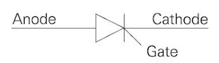
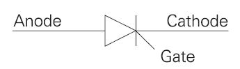
A primary function of a DC drive is to convert AC voltage into a variable DC voltage. It is necessary to vary to DC voltage in order to control the speed of a DC motor. A thyristor is one type of device commonly used to convert AC to DC. A thyristor consists of an anode, cathode, and a gate.
GATE CURRENT

A thyristor acts as a switch. Initially, a thyristor will conduct (switch on) when the anode is positive with respect to the cathode and a positive gate current is present. The amount of gate current required to switch on a thyristor varies. Smaller devices require only a few milliamps; however, larger devices such as required in the motor circuit of a DC drive may require several hundred milliamps.
HOLDING CURRENT

Holding current refers to the amount of current flowing from anode to cathode to keep the thyristor turned on. The gate current may be removed once the thyristor has switched on. The thyristor will continue to conduct as long as the anode remains sufficiently positive with respect to the cathode to allow sufficient holding current to flow. Like gate current, the amount of holding current varies from device to device. Smaller devices may require only a few milliamps and larger devices may require a few hundred milliamps.
The thyristor will switch off when the anode is no longer positive with respect to the cathode.
AC TO DC CONVERSION

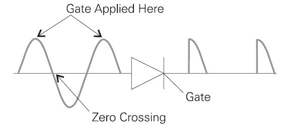
The thyristor provides a convenient method of converting AC voltage to a variable DC voltage for use in controlling the speed of a DC motor. In this example the gate is momentarily applied when AC input voltage is at the top of the sinewave. The thyristor will conduct until the input’s sinewave crosses zero. At this point the anode is no longer positive with respect to the cathode and the thyristor shuts off. The result is a half-wave rectified DC.
The amount of rectified DC voltage can be controlled by timing the input to the gate. Applying current on the gate at the beginning of the sinewave results in a higher average voltage applied to the motor. Applying current on the gate later in the sinewave results in a lower average voltage applied to the motor.
DC DRIVE CONVERTER

The output of one thyristor is not smooth enough to control the voltage of industrial motors. Six thyristors are connected together to make a 3Ø bridge rectifier.
GATING ANGLE

As we have learned, the gating angle of a thyristor in relationship to the AC supply voltage, determines how much rectified DC voltage is available. However, the negative and positive value of the AC sine wave must be considered when working with a fully-controlled 3Ø rectifier.
A simple formula can be used to calculate the amount of rectified DC voltage in a 3Ø bridge. Converted DC voltage (VDC) is equal to 1.35 times the RMS value of input voltage (VRMS) times the cosine of the phase angle (cosα).

VDC = 1.35 x VRMS x cosα

The value of DC voltage that can be obtained from a 460 VAC input is -621 VDC to +621 VDC. The following table shows sample values of rectified DC voltage available from 0° to 180°. It is important to note that voltage applied to the armature should not exceed the rated value of the DC motor.

The following illustration approximates the output waveform of a fully controlled thyristor bridge rectifier for 0°, 60°, and 90°. The DC value is indicated by the heavy horizontal line. It is important to note that when thyristors are gated at 90° the DC voltage is equal to zero. This is because thyristors conduct for the same amount of time in the positive and negative bridge. The net result is 0 VDC. DC voltage will increase in the negative direction as the gating angle (α) is increased from 90° to a maximum of 180°.

SPEED/TORQUE CURVES OF DC MOTORS

The diagram below compares speed/torque characteristics of DC motors. At the point of equilibrium, the torque produced by the motor is equal to the amount of torque required to turn the load at a constant speed. At lower speeds, such as might happen when load is added, motor torque is higher than load torque and the motor will accelerate back to the point of equilibrium. At speeds above the point of equilibrium, such as might happen when load is removed, the motor’s driving torque is less than required load torque and the motor will decelerate back to the point of equilibrium.


Types of DC Motors


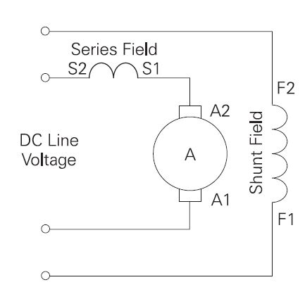
The field of DC motors can be a permanent magnet, or electromagnets connected in series, shunt, or compound.

PERMANENT MAGNET

 The permanent magnet motor uses a magnet to supply field flux. Permanent magnet DC motors have excellent starting torque capability with good speed regulation. A disadvantage of permanent magnet DC motors is they are limited to the amount of load they can drive. These motors can be found on low horsepower applications. Another disadvantage is that torque is usually limited to 150% of rated torque to prevent demagnetization of the permanent magnets.
SERIES MOTORS

In a series DC motor the field is connected in series with the armature. The field is wound with a few turns of large wire because it must carry the full armature current.
A characteristic of series motors is the motor develops a large amount of starting torque. However, speed varies widely between no load and full load. Series motors cannot be used where a constant speed is required under varying loads. Additionally, the speed of a series motor with no load increases to the point where the motor can become damaged. Some load must always be connected to a series-connected motor. Series-connected motors generally are not suitable for use on most variable speed drive applications.
SHUNT MOTORS

In a shunt motor the field is connected in parallel (shunt) with the armature windings. The shunt-connected motor offers good speed regulation. The field winding can be separately excited or connected to the same source as the armature. An advantage to a separately excited shunt field is the ability of a variable speed drive to provide independent control of the armature and field. The shunt-connected motor offers simplified control for reversing. This is especially beneficial in regenerative drives.
COMPOUND MOTORS

Compound motors have a field connected in series with the armature and a separately excited shunt field. The series field provides better starting torque and the shunt field provides better speed regulation. However, the series field can cause control problems in variable speed drive applications and is generally not used in four quadrant drives.