The sensor incorporates an electromagnetic coil which is used to detect the presence of a conductive metal object. The sensor will ignore the presence of an object if it is not metal.


When a metal target enters the field, eddy currents circulate within the target. This causes a load on the sensor, decreasing the amplitude of the electromagnetic field. As the target approaches the sensor the eddy currents increase, increasing the load on the oscillator and further decreasing the amplitude
of the field. The trigger circuit monitors the oscillator’s amplitude and at a predetermined level switches the output state of the sensor from its normal condition (on or off). As the target moves away from the sensor, the oscillator’s amplitude increases. At a predetermined level the trigger switches the output state of the sensor back to its normal condition (on or off).

inductive proximity sensors include AC, DC, and AC/ DC (universal voltage) models. The basic operating voltage ranges are from 10 to 30 VDC, 15 to 34 VDC, 10 to 65 VDC, 20 to 320 VDC, and 20 to 265 VAC.
DIRECT CURRENT DEVICES
Direct current models are typically three-wire devices (two-wire also available) requiring a separate power supply. The sensor is connected between the positive and negative sides of the power supply. The load is connected between the sensor and one side of the power supply. The specific polarity of the connection depends on the sensor model. In the following example the load is connected between the negative side of the power supply and the sensor.
OUTPUT CONFIGURATION
Three-wire, DC proximity sensor can either be PNP (sourcing) or NPN (sinking). This refers to the type of transistor used in the output switching of the transistor. The following drawing illustrates the output stage of a PNP sensor. The load is connected between the output (A) and the negative side of the power supply (L-). A PNP transistor switches the load to the positive side of the power supply (L+). When the transistor switches on, a complete path of current flow exists from L- through the load to L+. This is also referred to as current sourcing since in this configuration conventional
current is (+ to -) sourced to the load. This terminology is often confusing to new users of sensors since electron current flow (- to +) is from the load into the sensor when the PNP transistor turns on.


NORMALLY OPEN, NORMALLY CLOSED
Outputs are considered normally open (NO) or Normally Closed (NC) (NC) based on the condition of the transistor when a target is absent. If, for example, the PNP output is off when the target is absent then it is a normally open device. If the PNP output is on when the target is absent it is a normally closed device.
COMPLEMENTARY
Transistor devices can also be complementary (four-wire). A complementary output is defined as having both normally open and normally closed contacts in the same sensor.

SHIELDING
Proximity sensors contain coils that are wound in ferrite cores. They can be shielded or unshielded. Unshielded sensors usually have a greater sensing distance than shielded sensors.

The ferrite core concentrates the radiated field in the direction of use. A shielded proximity sensor has a metal ring placed around the core to restrict the lateral radiation of the field. Shielded proximity sensors can be flush mounted in metal. A metal-free space is recommended above and around the
sensor’s sensing surface. Refer to the sensor catalog for this specification. If there is a metal surface opposite the proximity sensor it must be at least three times the rated sensing distance of the sensor from the sensing surface.
UNSHIELDED PROXIMITY SENSORS
An unshielded proximity sensor does not have a metal ring around the core to restrict lateral radiation of the field. Unshielded sensors cannot be flush mounted in metal. There
must be an area around the sensing surface that is metal free. An area of at least three times the diameter of the sensing surface must be cleared around the sensing surface of the sensor. In addition, the sensor must be mounted so that the metal surface of the mounting area is at least two times the
sensing distance from the sensing face. If there is a metal surface opposite of the proximity sensor it must be at least three times the rated sensing distance of the sensor from the sensing surface.
MOUNTING MULTIPLE SENSORS
Care must be taken when using multiple sensors. When two or more sensors are mounted adjacent to or opposite one another, interference or cross-talk can occur producing false outputs. The
following guidelines can generally be used to minimize interference.
• Opposite shielded sensors should be separated by at least four times the rated sensing range
• Opposite unshielded sensors should be separated by at least six times the rated sensing range
• Adjacent shielded sensors should be separated by at least two times the diameter of the sensor face
• Adjacent unshielded sensors should be separated by at least three times the diameter of the sensor face.
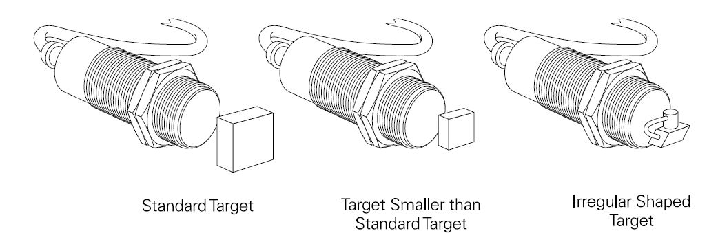
STANDARD TARGET
A standard target is defined as having a flat, smooth surface, made of mild steel that is 1 mm (0.04”) thick. Steel is available in various grades. Mild steel is composed of a higher content of
iron and carbon. The standard target used with shielded sensors has sides equal to the diameter of the sensing face. The standard target used with unshielded sensors has sides equal to the diameter of the sensing face or three times the rated operating range,whichever is greater. If the target is larger than the standard target, the sensing range does not change. However, if the target is smaller or irregular
shaped the sensing distance (Sn) decreases. The smaller the area of the target the closer it must be to the sensing face to be detected.
TARGETING SIZE CORRECTION FACTOR
A correction factor can be applied when targets are smaller than Correction Factor the standard target. To determine the sensing distance for a target that is smaller than the standard target (Snew), multiply
the rated sensing distance (Srated) times the correction factor (T). If, for example, a shielded sensor has a rated sensing distance of 1 mm and the target is half the size of the standard target, the new sensing distance is 0.83 mm (1 mm x 0.83).
Snew = Srated x T
Snew = 1 mm x 0.83
Snew = 0.83 mm

Thickness of the target is another factor that should be considered. The sensing distance is constant for the standard target. However, for nonferrous targets such as brass, aluminum, and copper a phenomenon known as “skin effect” occurs. Sensing distance decreases as the target thickness
increases. If the target is other than the standard target a correction factor must be applied for the thickness of the target.

TARGET MATERIAL
The target material also has an effect on the sensing distance. When the material is other than mild steel correction factors need to be applied.

RATED OPERATING DISTANCE
The rated sensing distance (Sn) is a theoretical value which does not take into account such things as manufacturing tolerances, operating temperature, and supply voltage. In some applications the sensor may recognize a target that is outside of the rated sensing distance. In other applications the target may not be recognized until it is closer than the rated sensing distance. Several other terms must be considered when evaluating an application.
The effective operating distance (Sr) is measured at nominal supply voltage at an ambient temperature of 23°C ± 0.5°. It takes into account manufacturing tolerances. The effective
operating distance is ±10% of the rated operating distance. This means the target will be sensed between 0 and 90% of the rated sensing distance. Depending on the device, however, the
effective sensing distance can be as far out as 110% of the rated sensing distance.
The useful switching distance (Su) is the switching distance measured under specified temperature and voltage conditions. The useful switching distance is ±10% of the effective
operating distance. The guaranteed operating distance (Sa) is any switching distance for which an operation of the proximity switch within specific permissible operating conditions is guaranteed. The
guaranteed operating distance is between 0 and 81% of the rated operating distance.
RESPONSE CHARACTEERISTICS
Proximity switches respond to an object only when it is in a defined area in front of the switch’s sensing face. The point at which the proximity switch recognizes an incoming target is the
operating point. The point at which an outgoing target causes the device to switch back to its normal state is called the release point. The area between these two points is called the hysteresis zone.


No comments:
Write comments